Position:
/
Design Guide : Urethane Casting
Overview
Urethane Casting provides end-use, rigid or flexible plastic parts with production-level quality. Built without expensive and time-consuming hard tooling, our urethane casting process uses a 3D printed master pattern and silicone molds to deliver high-quality, short-run parts up to 30” long.
The finished dimensions of urethane cast parts depends on the accuracy of the master model, part geometry and casting material. In general, a shrinkage rate of +0.15% is expected.
The finished dimensions of urethane cast parts depends on the accuracy of the master model, part geometry and casting material. In general, a shrinkage rate of +0.15% is expected.


Typical Build Process
STEP 1: First a master pattern is printed in either PolyJet 3D (PJ3D) or Stereolithography (SLA) to provide an accurate silicone mold. Sometimes tape is placed on flat surfaces to allow for crisp, clean removal of the cast part during post-processing.

STEP 2: Next, the master pattern is encased in liquid silicone to form an accurate mold.

STEP 3: After the mold cures it is cut into distinct halves and the pattern is removed. This cavity is used for casting the end product. Note that features that may fatigue, such as through holes, are replaced with dowels.

STEP 4: Once the mold tool is created our production team will use urethane and other resins to fill the voids. The material will cure and be removed from the tool. This process repeats until the project is finished!

Features
RibsAdding ribs to a design is an excellent way to improve the strength and rigidity of molded parts. Adding this type of reinforcement will decrease the part's ability to bend (increasing the bending stiffness) without having to make the part thicker.
GUIDELINES
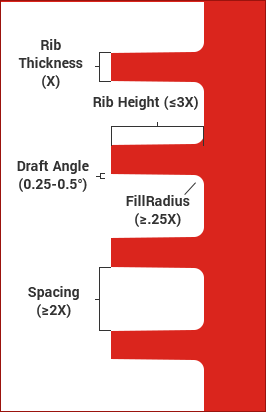
• Height: Generally, the length of the rib determines the rib strength so a longer rib will provide greater reinforcement. Unfortunately, when casting in urethane a long rib can be difficult to mold. As a result, HLH recommends that the rib does not exceed a height of 3 times its thickness to ensure that the part does not deviate from the design.
• Width: The width of a rib at the intersection with the part should range from 40 to 60% of the thickness of the part, with fillet radius of at least 25% of the thickness of the part to ensure the maximum rib strength.
• Draft Angle: It is important to draft a rib to reduce the possibility of sinking. HLH recommends making the draft angles of each side between 0.25 and 0.5 degrees. The draft angle of each side should be equal.
Ribs(Continued) GUIDELINES
• Spacing: HLH recommends spacing consecutive ribs at least 2 times the thickness away from each other to maximize the impact of each rib.
• Orientation: Ribs should be oriented in a way that maximizes the bending stiffness of the part. This depends on how and where the load or stress will be placed on the part. If the ribs are oriented in the wrong direction they will have little to no effect on the stiffness.
INTERSECTIONS & SINKING
At the intersection of where a rib meets a part lies the possibility of the part to dip due to a heavy rib weighing down the surface.
These are some of the ways to reduce the risk of sinking at a rib intersection:
• Fillets: HLH recommends making the radii of fillets at least one quarter of the thickness of the part. Fillets reduce the stress on the surface and can reduce sink on the opposite side of the part.
• Coring (lightweighting) the part will reduce material as well as help maintain a uniform wall thickness throughout the part.
• Rib thickness: At a rib intersection, the width of the rib should only be 40 to 60% of the thickness of the part. Thinning down the walls will avoid excess sinking on the opposite side by decreasing the weight of the rib.
GUIDELINES
• Height: Generally, the length of the rib determines the rib strength so a longer rib will provide greater reinforcement. Unfortunately, when casting in urethane a long rib can be difficult to mold. As a result, HLH recommends that the rib does not exceed a height of 3 times its thickness to ensure that the part does not deviate from the design.
• Width: The width of a rib at the intersection with the part should range from 40 to 60% of the thickness of the part, with fillet radius of at least 25% of the thickness of the part to ensure the maximum rib strength.
• Draft Angle: It is important to draft a rib to reduce the possibility of sinking. HLH recommends making the draft angles of each side between 0.25 and 0.5 degrees. The draft angle of each side should be equal.
Ribs(Continued) GUIDELINES
• Spacing: HLH recommends spacing consecutive ribs at least 2 times the thickness away from each other to maximize the impact of each rib.
• Orientation: Ribs should be oriented in a way that maximizes the bending stiffness of the part. This depends on how and where the load or stress will be placed on the part. If the ribs are oriented in the wrong direction they will have little to no effect on the stiffness.
INTERSECTIONS & SINKING
At the intersection of where a rib meets a part lies the possibility of the part to dip due to a heavy rib weighing down the surface.
These are some of the ways to reduce the risk of sinking at a rib intersection:
• Fillets: HLH recommends making the radii of fillets at least one quarter of the thickness of the part. Fillets reduce the stress on the surface and can reduce sink on the opposite side of the part.
• Coring (lightweighting) the part will reduce material as well as help maintain a uniform wall thickness throughout the part.
• Rib thickness: At a rib intersection, the width of the rib should only be 40 to 60% of the thickness of the part. Thinning down the walls will avoid excess sinking on the opposite side by decreasing the weight of the rib.
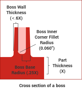
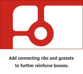
Bosses
Bosses are an excellent feature to secure mating parts with screws or fasteners. The base radius of the boss should be 25% of the thickness of the part to prevent the screw or pin from burning when placed into the boss. To reduce the wall thickness and avoid sinking, inner corners of bosses can use a 0.060" radius for the fillet. HLH recommends making the wall thickness for bosses less than 60% of the thickness of the part to ensure minimal shrinkage.
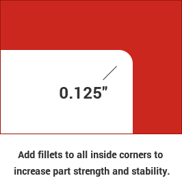
Radii & Fillets
HLH recommends a fillet with a radius of 0.125" on all inside corners, or surface transitions to increase the strength of the part.
Inserts
Through holes: For simple through holes, dowel rods are placed into the silicone mold to define the feature. Maintaining a line of sight is required when designing for urethane casting to ensure that a dowel rod can be inserted in the mold.
Threads: Threaded inserts can be added to a urethane casting mold in a variety of sizes. To learn more about the features that can be inserted in a urethane casting mold please contact our engineers at support@hlhmold.com.
Threads: Threaded inserts can be added to a urethane casting mold in a variety of sizes. To learn more about the features that can be inserted in a urethane casting mold please contact our engineers at support@hlhmold.com.