Position:
/

Introduction to MJF 3D Printing

What is MJF 3D printing?
MJF selectively applies fusing and detailing agents across a bed of nylon powder, which are fused in thousands of layers by heating elements into a solid functional component.
Design of MJF 3D printing
Design guidelines applicable for MJF 3D printing processes. Design guidelines for specific processes. Design guidelines for specific parts.

Our MJF 3D Printing Service

Multi Jet Fusion (MJF) is HP's proprietary 3D printing process. In MJF, parts are built by jetting a binding agent onto thin layers of polymer powder particles (typically nylon) and then sintering them using an IR heat source. MJF produces functional plastic parts with isotropic mechanical properties that can be used for detailed prototyping or end-use low-volume production.

Our <span style="color:#DA251D">MJF</span>  3D Printing Service

PRODUCTION CAPACITY

Maximum build size:

380 × 280 × 380 mm

Standard lead time:

2-3 business days

Dimensional accuracy:

± 0.5% with a lower limit of ± 0.15 mm (± 0.006")

Layer height:

25-100 um

Advantages of MJF

Fast speed
High quality printouts
High-precision
Low cost
High density and low porosity

Available Materials For MJF

Material
Material Reference
Colors
Specifications / Type
PA
PA12
Black
380*280*380mm
PA+GF
FS3400GF
Black
380*280*380mm

Post Processing For MJF

Deburr
Painting
Polishing
Sand blasting
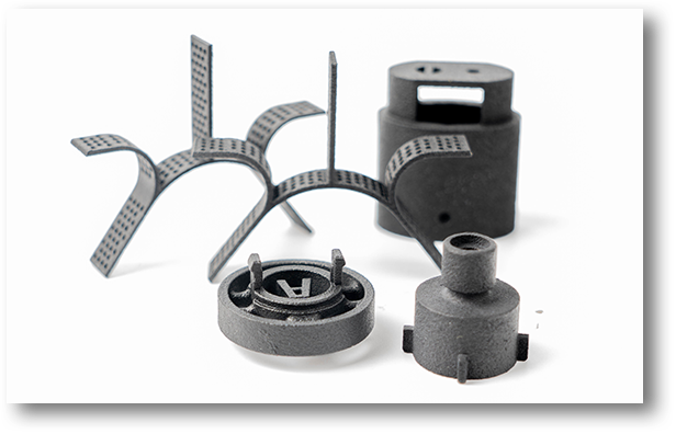
Design Guidelines For MJF
TIPS & TRICKS
Wall thicknesses from 2.5 to 3.8 mm are ideal
Susceptible to warping, large flat areas must be avoided
Thin-walled or large, flat surfaces should be reinforced with ribs or gussets
TOLERANCES
± 0.2mm is standard.
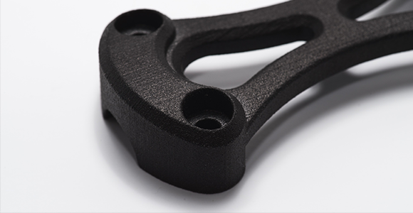
TOLERANCES
WALLS
HLH recommend a wall thickness of at least 1 mm. Large parts may require larger wall thicknesses or added ribs or fillets for reinforcement.
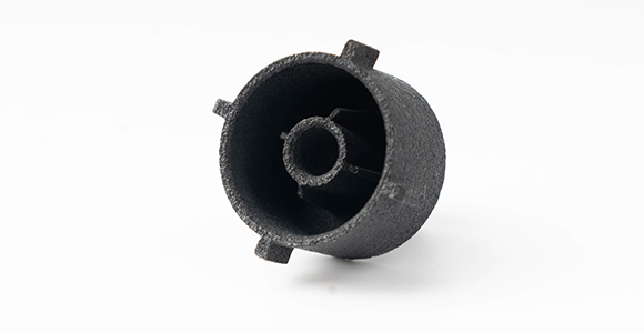
WALLS
HOLLOWING
We advise hollowing out a solid model as much as possible, and when the wall thickness exceeds 20 mm. This will save material and prevent sink marks. Holes is 2 mm, with a minimum of 1 mm.
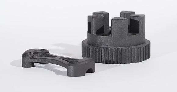
HOLLOWING
MATING PARTS
Minimum 0.5mm gap between axel and bore or other moving parts.
MATING PARTS
EMBOSSED AND ENGRAVED DETAILS
For embossed or engraved textures, we advise a minimum thickness of
0.25 mm. We recommend letters with a minimum line thickness of
0.5 mm, a depth of 1 mm, and an overall height of at least 2.5 mm.
EMBOSSED AND ENGRAVED DETAILS