Position:
/

Introduction to SLS 3D Printing

What is SLS 3D printing?
SLS uses a CO2 laser that fuses nylon-based powder, layer by layer until final thermoplastic parts are built.
Design of SLS 3D printing
Design guidelines applicable for SLS 3D printing processes. Design guidelines for specific processes. Design guidelines for specific parts.

Our SLS 3D Printing Service

Selective Laser Sintering or SLS is an industrial 3D printing technology with builds accurate and durable parts from nylon (PA 12) materials. SLS is used extensively for prototypes and production. Similar to other technologies it builds parts layer by layer from a powder material. Due to the powder surrounding the part as it is built SLS can realise overhangs and complex features without support structures.

Our <span style="color:#DA251D">SLS</span>  3D Printing Service

PRODUCTION CAPACITY

Maximum build size:

400 × 400 × 450 mm

Standard lead time:

2-3 business days

Dimensional accuracy:

± 0.5% with a lower limit of ± 0.15 mm (± 0.006")

Layer height:

25-100 um

Advantages of SLS

Self-supporting, no support required
High strength parts
Chemical resistance
Accurate to CAD
Fast build times
No tooling costs
Complex geometries possible

Available Materials For SLS

Material
Material Reference
Colors
Specifications / Type
PA
FS3300PA
white/Black
400*400*450mm
PA+GF
FS3400GF
Grey/Black/White
400*400*450mm
High strength
TPU
White
500*500*400mm

Post Processing For SLS

Deburr
Painting
Dye
Sand blasting
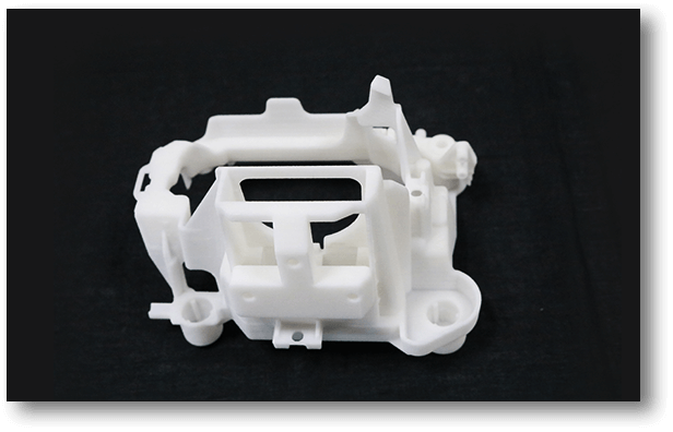
Design Guidelines For SLS
TIPS & TRICKS
Hollow parts out with escape holes for trapped materials. Anneal living hinges by dipping in boiling water and work back and forth.
TOLERANCES
± 0.2mm is standard.
PINS
Standard tolerance is +/- 0.3mm so any features with dimensions below this are unlikely to be printed without issue. So pins should be designed ≥ 0.8mm.
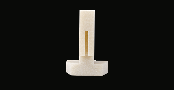
PINS
SLOTS
Effected by depth or thickness of the wall, ≥ 0.5mm is minimum but will fail to print if the depth or wall thickness is over 2mm.
SLOTS
HOLES
The deeper the hole the larger the diameter needed. All holes should be ≥ 1mm. Blind holes should be designed with an escape hole to remove powder.
HOLES
MATING (AXELS, GEARS)
> 0.5mm and < 1mm gaps prevent fusion.
Min Clearance: > 0.5mm
Max Clearance: < 1.0mm
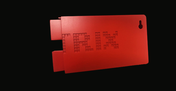
MATING (AXELS, GEARS)
TEXT
Sans serif such as Arial with a minimum font height of 2mm.
Embossed text: > 1mm high.
Engraved features: > 1mm deep.
TEXT